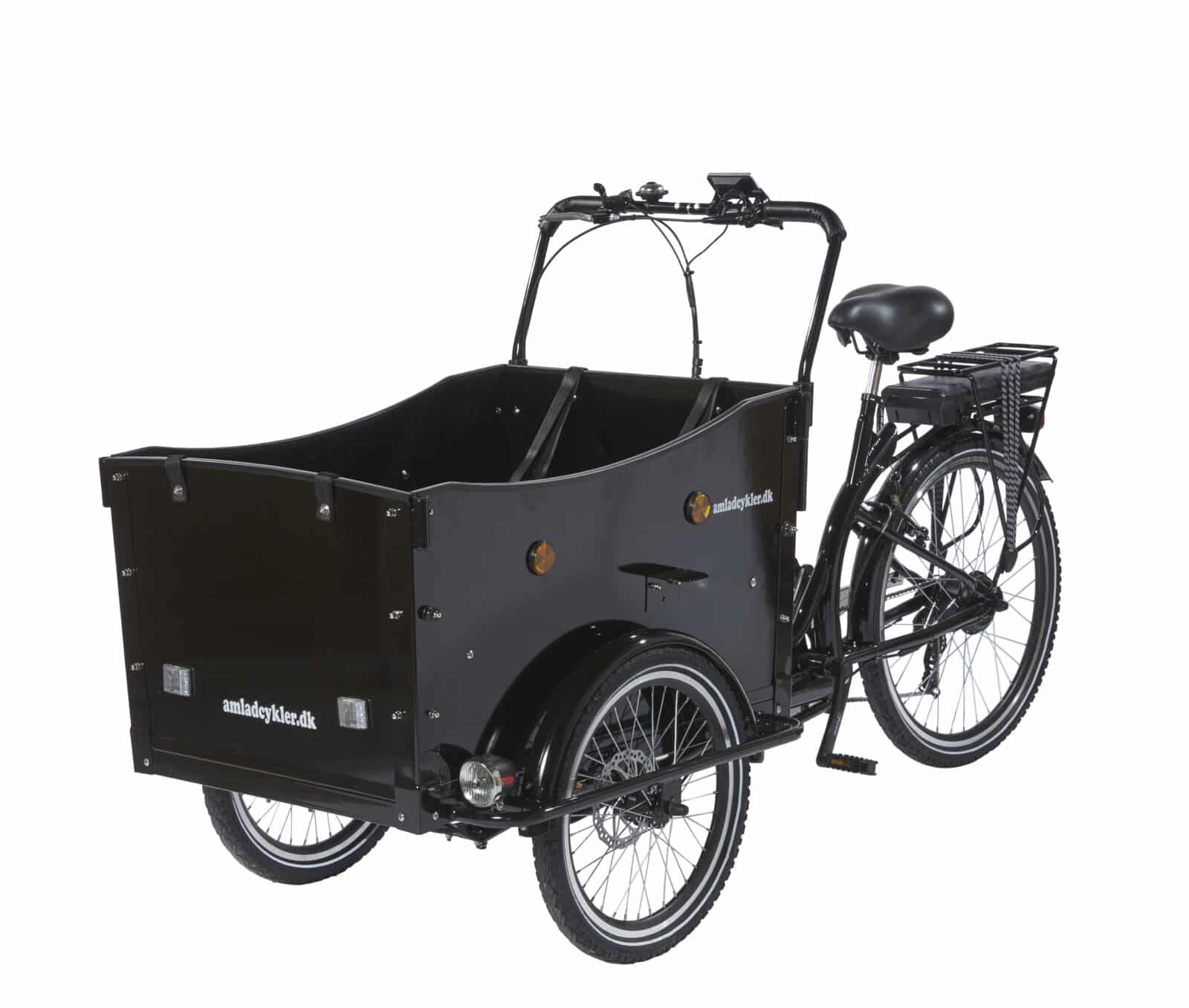
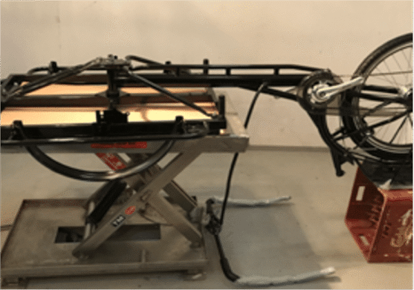
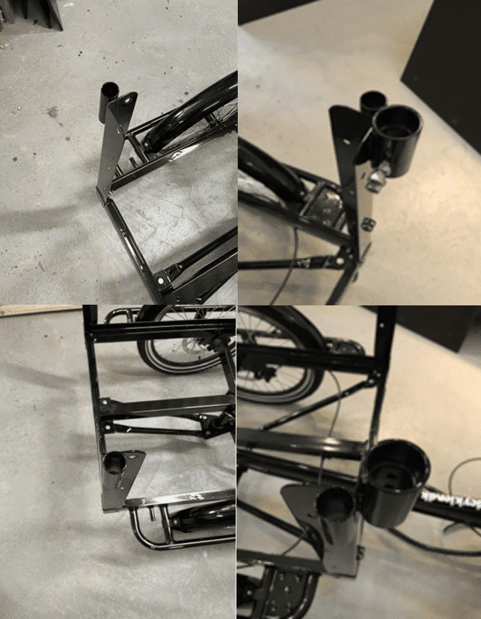
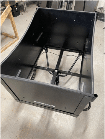
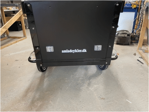
Assemble Instruction for our Electric Cargo Bike - Deluxe

Read and understand these instructions before you begin the assembly. The bike comes partly assembled, and it is important to read the manual carefully before starting  assembly, so the bicycle will be assembled in the correct order. It is recommended to be  two people to assemble the cargo bike. Be aware that the bike must be re-tightened after  approx. 20 km. Make sure to check all parts of the bike and re-tighten all moving parts, including brakes, spokes, bolts and nuts.

Electric Cargo Bike - Deluxe

Step 1: Assembly of the back and front frame

Parts you need in step 1

  • 7 pc. 13 mm bolts (length: 25 mm)
  • 7 pc. washers
  • 7 pc. 13 mm nuts
  1. When the parts have been taken out of the boxes and wrapping, place the front frame upside down on two chairs (see picture 1A).
  2. Place the back frame upside down “on top” of the front frame. Avoid taking the plastic on the luggage carrier off to avoid scratches in the paint.
  3. With the 7 large bolts, washers and nuts mount the bow-shaped and the two straight metal rods as shown on image 1C, 1D and 1E. The metal rods must be placed below the trazezodial plate and on top of the frame as shown in the pictures(It is important that all parts are assembled before tightening nuts, etc.). In order to avoid that the stainless steel locknuts get stuck  halfway down on the bolt, use some grease at the end of the bolts, before the nut is tightened.
  4. Only when these are tightened, tighten the large nut on the main bolt as hard as possible, and insert the split (see picture 1F).

Picture 1A

Picture 1B

Picture 1C

Picture 1D

Picture 1E

Picture 1F

Step 2: Fenders, front wheels and brake pads

Parts you need in step 2

  • 8 pc. 8 mm bolts (length: 12 mm)
  • 8 pc. washers
  • 8 pc. 8 mm nuts
  • 2 glossy umbraco bolts with washers
  • 4 black umbraco bolts with 2-3 extra slices
  1. One of the chairs is moved to the end of the front frame and the second chair is removed.
  2. The front fenders are mounted with 8 small bolts, washers, and nuts + the four brackets (see picture 2A and 2B). To make sure that the fenders are just above the wheels, the nuts are tightened after the wheels are mounted.
  3. The brake discs are mounted on the front wheels with the 2 x 6 small black torx bolts – see picture 2C.
  4. Mount the front wheels as in picture 2D.
  5. The brake cable / brake calibers are mounted. First install the distributor with the two glossy umbraco bolts. Note that this must be the opposite of what you expect (see picture 2E).
  6. Then mount the two brake calibers with the four black umbraco bolts. Note: use 2-3 extra washers per Allen bolt to ensure good distance from the end of the screw to the brake disc. See Figures 2F.
  7. The position of the brake calibers versus the brake discs are adjusted via the blank umbraco-disc on the outside of the caliber and the side-by-side adjustment bolts on the brake caliber. The brake discs should in this way run freely without touching the brake pads when the wheel is turned. It is however OK if there is a small ”whisling” sound from the brake when the wheel is turned – this will disappear after a few days of use.
  8. Then the bike is turned around.

Picture 2A

Picture 2B

Picture 2C

Picture 2D

Picture 2E

Picture 2F

Step 3: Assemble the box

Parts you need in step 3

  • 8 pc. 10 mm bolts (length 30 mm)
  • 8 pc. washers
  • 8 pc. 10 mm lock nuts
  • 20 pc. 10 mm bolts (length 18 mm)
  • 20 pc. washers
  • 20 pc. 10 mm rounded nuts
  • 4 pc. 10 mm boltt (length 30 mm)
  • 4 plastic elements for canopy-mounting
  • 4 pc. washers
  • 4 pc. 10 mm rounded nuts
  • 2 pc. 10 mm bolts (length 70 mm)
  • 2 pc. washers
  • 2 pc. 10 mm lock nuts
  • 2 pc. Small bolts
  • 2 pc waschers
  • 2 pc. step boards
  • 4 pc. 10 mm bolts (length 18 mm)
  • 4 pc. washers
  • 4 pc. 10 mm rounded nuts
  • 4 pc. yellow side-reflectors
  • 2 pc. white front-reflectors
  • 2 pc. red back-reflectors
  1. The corner brackets for the box are mounted as shown in picture 3A – with the nuts on the inside.
  2. The correct position of the four different corner fittings is shown on picture 3B.

The following is mounted loosely and tightened in the end:

    1. The front and back panels are mounted (see picture 3C) with 12 og the 10 mm bolts, washers and rounded nuts as illustrated below – with the nuts on the outside.
    2. The side panels are mounted (see picture 3D) with the remaining 8 of the 10 mm bolts, washers and rounded nuts. The four canopy holders are mounted with the long bolts in the holes in the middle (see picture 3E below). All nuts on the outside.
    3. The base panel is mounted with the long bolts and the nuts on the bottom side. The two small bolts are used in the front and back hole in the bottom plate (see picture 3F).
    4. And then all bolts and nuts are tightened.

Picture 3A

Picture 3B

Picture 3C

Picture 3D

Picture 3E

Picture 3F

Picture 3G

Picture 3H

Picture 3I

Step 4: The rest of the equipment

Parts you need in step 4

  • 4 pc. 10 mm bolts (length 40 mm)
  • 4 pc. waschers
  • 4 pc. 10 mm lock nuts
  • 8 pc. 10 mm bolts (length 18 mm)
  • 8 pc. washers
  • 8 pc. 10 mm lock nuts
  1. The headlights are mounted on the sides of the box (see picture 4A) with the two last 8 mm bolts (same type as for the front fenders).
  2. The pedals are mounted (see picture 4B) – note that they have left-thread and that the pedals have  left / right markings.

  3. The four bolts which supports the child seat holders are mounted (see picture 4C).

  4. The child seats are mounted with four screws (see picture 4D). The seat belts are mounted on the outside of the box (front- and back panel) and below the child seats (see picture 4E).
  5. The plastic fittings for the steer and the canopy-holders are mounted with a small hammer (see picture 4F and 4G).
  6. The plastic-fittings for the wheel nuts are mounted with a small hammer (ses picture 4H).
  7. The saddle is mounted on the saddle post and this is mounted on the bike (see picture 4I)
  8. The handlebar is mounted and the break handles, gear shifter, display and bell are mounted on the handlebar (see picture 4J, 4K, 4L, 4M).

Picture 4A

Picture 4B

Picture 4C

Picture 4D

Picture 4E

Picture 4F

Picture 4G

Picture 4H

Picture 4I

Picture 4J

Picture 4K

Picture 4L

Picture 4M

Picture 4N

Step 5: Brake cables and adjustment of brakes and gear

  1. The back brake is adjusted by using the two adjustment-bolts, making sure that the brake pads in the brake caliber is not touching the brake disc when the wheel is rotated – see picture 5A and 5B.
  2. Attach the brake cable with the cable holder (see pictures 5C and 5D).
  3. The gear is tested. If the gear ”clicks” or you experience difficulties in changing gear, you can adjust the gear by using the small black ”hand-screw” where the gear cable is mounted on the gear shift (see picture 5E).

Picture 5A

Picture 5B

Picture 5C

Picture 5D

Picture 5E

IMPortant info

  • The frame number is stamped into the frame on the left side of the bike – just in front of the left pedal.
  • Remember to adjust and re-tighten all moving parts on the bike after some weeks of use. If re- tightening of the spokes are needed, please use a spoke tightener.
  • See our guides on https://amladcykler.com/assembly-and-maintenance-manuals/?v=0ecbf9426bcf

Enjoy your new cargo bike...!